Mounting the MicaSense RedEdge 3 to a DJI M600
Introduction:
This writeup is an explanation of the design and 3D printing process used to create a mount for the MicaSense RedEdge 3 on the DJI M600. The only design parameters given were that the RedEdge would have to be easily removable using a Slick DQ-10 Quick Release Adapter and the mount could not interfere with another RGB sensor mounted to the front of the M600’s payload rack.
Design Process:
The design software used was Fusion 360 a powerful and agile design software created by Autodesk. I chose to use Fusion 360 because of its built in keyboard shortcuts, seamless integration into other utilities, and the ability to work offline. (I am a Purdue student and while I do have access to other design programs I must remote into the Purdue network to access them).
I began by examining the Slick DQ-10 Quick Release Adapter to see how it functioned then I replicated a simplified version in CAD. The Slick DQ-10 uses angles to lock the plate (shown in black) between the body (shown in white) and the cam (shown in blue) (see figure 1). The cam has a spring to keep the plate locked in place. To release the plate, the cam can be rotated and it will release the plate.
 |
| Figure 1: Slick DQ-10 Quick Release Adapter |
With the information on how the Slick DQ-10 worked, I located the RedEdge Integration Guide and used the attachment points drawing (see figure 2) to create an interface between the Slick DQ-10 body and the RedEdge mounting holes (see figure 3).
 |
| Figure 2: RedEdge Attachment Points Drawing (source: https://support.micasense.com/hc/en-us/articles/226364087-RedEdge-Integration-Guide) |
 |
| Figure 3: Interface Between RedEdge and Slick DQ-10 Quick Release Adapter Body |
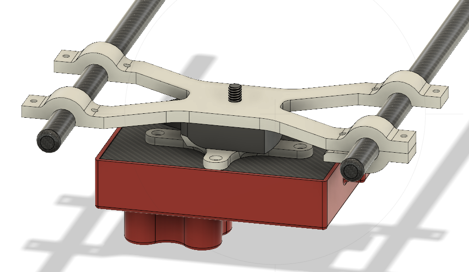
Once the interface was created, a bracket had to be created to connect the DJI M600 mounting rails to the Slick DQ-10 Quick Release Adapter body. The rails were 12mm in diameter and the distance between them was measured at 149.4mm. Using this information, an X shaped bracket was created to hang from the rails (see figure 4). The bracket was intentionally designed to hang so that if any bottom bracket (shown in green) were to come off, the sensor would still be attached to the rails and would not fall.
 |
| Figure 4: X-Bracket and Bottom Brackets |
To attach the bottom brackets to the X-bracket, 8 4-40 ½ inch screws and 8 4-40 nuts were used. Figure 5 below shows the bottom brackets with their cutouts for the 4-40 nuts.
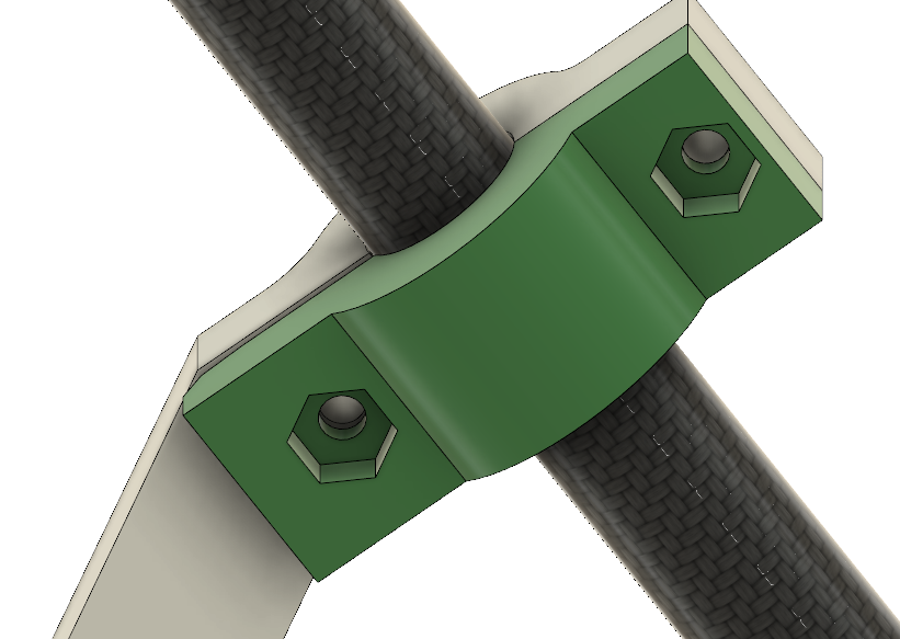 |
| Figure 5: Bottom Bracket |
3D Printing Process:
The process of 3D Printing these parts was fairly simple. The 3D printer used was a Zortrax M200 which comes with its own proprietary software called Z-Suite. Within the printing application, I imported the X-bracket, bottom bracket and interface as STL files and went through the user interface to print them. The material used was Z-Ultrat and the settings used were 20% infill, a layer thickness of 0.09 and, auto supports. Figure 6 below shows the Z-Suite settings used.
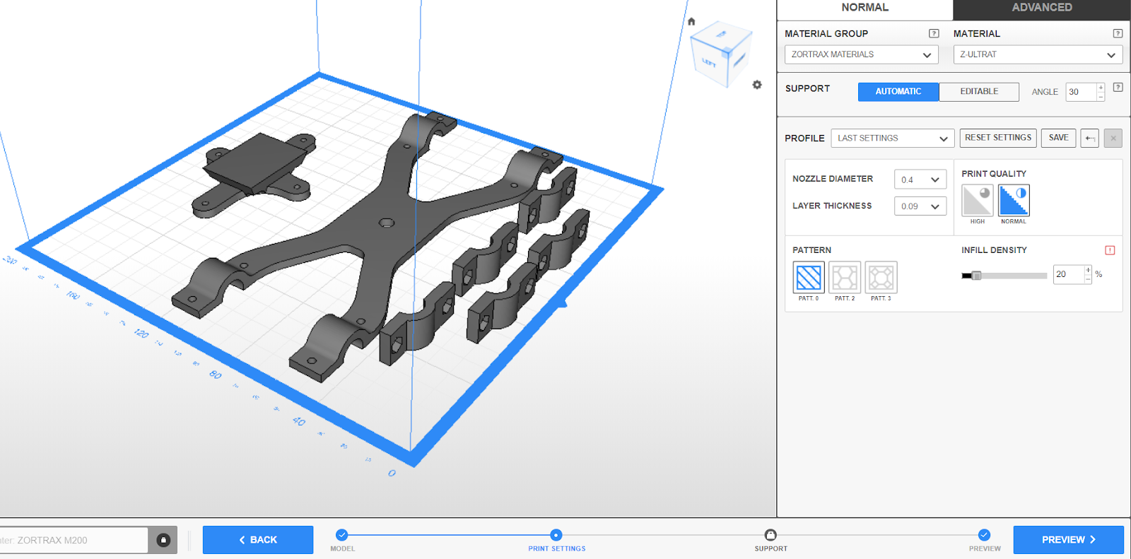 |
| Figure 6: Setting up Z-Suite |
Mounting the Downwelling Light Sensor and GPS unit:
Once all of the 3D printed parts were mounted, the downwelling light sensor and GPS unit were mounted on a foldable mast purchased on Amazon.
 |
| Figure 7: Foldable GPS and DLS Mast |
Parts List and STL Files:
- 8 4-40 1/2inch screws
- 8 4-40 lock nuts
- 4 4-40 5/16inch flat head screws
- 1 Slick DQ-10 Quick Release Adapter
- 1 X-Bracket
- 4 Bottom brackets
- 1 Interface between RedEdge and RQ-10 slick mount
- DLS and GPS mast
 |
| Figure 8: RedEdge Mounted on DJI Matrice 600 |